We can calculate current, voltage, and resistance through a clamp meter. These three are the basic parameters for an electric circuit. However, our quest continues to make clamp meters more advanced.
The electric power is another important electrical parameter. Keeping its importance in view, the manufacturer installed the power measuring capability in the clamp meters.
We can use a clamp meter to measure electric power by measuring voltage across the load and current. If the load is pure resistive, we get power by multiplying voltage and current. However, measuring the power factor is a must for an inductive or capacitive load. Then we multiply the power factor with the product of voltage and current. A power meter or a power factor meter can be used to calculate the power factor for an inductive or capacitor load.
Don’t get confused. We are going to discuss the whole process in detail.
How to Measure Watt with a Clamp Meter?
In electric circuits, power calculation is significant for circuit analysts. We can use a clamp meter for measuring electric power. However, the nature of the load must be kept in mind.
In a DC circuit, the nature of the circuit does not matter for calculating power. We cannot say the same for AC circuits.
Measuring Power Using a Clamp Meter
Every clamp meter can be used for measuring resistive load. Things get complicated for inductive and capacitive loads where the power factor starts kicking.
Without the power factor, we cannot calculate the accurate electric power. Here, a special clamp meter enters the arena.
Important Terms to Understand
Before starting our discussion, we must discuss a few parameters. These parameters are used either for calculating electric power or to help in the calculation.
1. Electric Power
Electrical power is the rate of electrical energy supplied to a circuit. It is measured in Watts(W), kilowatts (kW), and kilowatts-hr. We can calculate power by using the following formula:
P=IV cos(𝝓)
In the above formula, P stands for power, I stands for current, V stands for voltage, and 𝝓 is the phase difference between I and V.
Let’s discuss the phase difference…
2. Phase Difference
The difference in the starting points of two signals is called phase difference. It is the simplest definition of phase difference. We represent phase difference by 𝝓.
Generally, the phase difference is valued in angles. The angles may be in degrees (like 90°) or in radiant (like 𝛑/2).
Phase difference plays a crucial role in the measurement of power. It is used for the calculation of the power factor.
Let’s study about power factor…
3. Power Factor
The power factor may be defined through different approaches:
- The ratio of real power to apparent power
- The cos ratio of phase difference i-e cos(𝝓)
- The ratio of resistance to the impedance
In all cases, we calculate the ratio that swings from 0 to 1. When the power factor is 0, the load is either pure inductive or capacitive which is bad and not practical. The power factor of 1 is the best scenario.
The resistive load has a power factor of 1. For the best practical inductive or capacitive load, the value of the power factor will lie near 1.
Power factor may be lagging or leading.
Types of Electric Loads
Electric loads are resistive in DC circuits. We can calculate power by just multiplying current and voltage across the corresponding load. Both voltage and current can be found easily through a clamp meter.
When it comes to AC circuits, electric loads are divided into three main categories due to the power factor of loads.
Let’s discuss each in detail…
1. Resistive Load
This type of load consists only of resistors. These resistors dissipate electric energy in the form of light, heat, or other forms of energy.
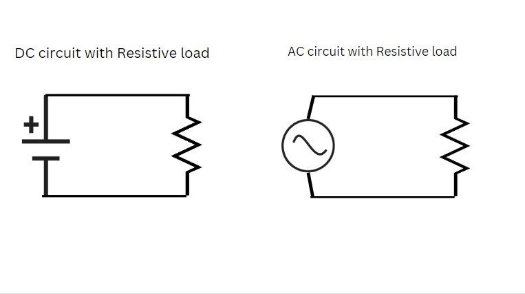
We can find electric power easily through resistive loads. All we need is the amount of voltage across the load and the amount of current passing through the load.
By simply multiplying, we can calculate the power in the corresponding load. This method applies to both AC and DC circuits.
2. Capacitive Load
When the current lead voltage is in a load, this circuit is known as a capacitive load. The power factor of this load is called the leading power factor. The phase difference between current and voltage affects the power factor.
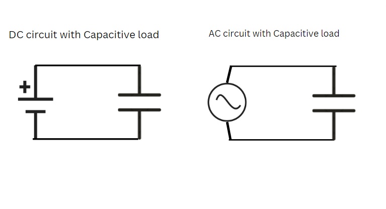
A pure capacitive load has a phase difference of 90° angle. It means the current is in advance than the voltage with a difference of 90°. However, the practical value is always less than 90°.
To find the electric power, the power factor of the capacitive load is multiplied by the product of voltage and current. If the power factor is ignored, the value of power will no longer be accurate.
3. Inductive Load
Here, the voltage leads to the current. The load may be called inductive or lagging. The power factor is added with the term “lagging” while measuring. This phase difference also impacts the power factor.
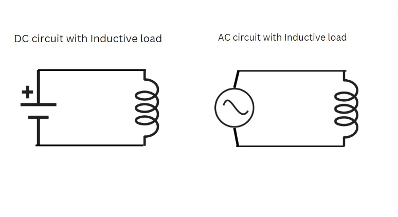
Likewise, a pure inductive load leads voltage from current by 90°. Again, this value is theoretical, not practical.
The value of the power factor also impacts the electric power here. We have to consider the power factor for accurate reading.
We thoroughly understood each scenario. Let’s calculate the electric power in each…
Power Measurement
We will focus on the method to measure power in inductive or capacitive load. We have already mentioned the resistive load in the previous topic. The following are the measuring parameters for electric power.
- Voltage across the load
- Current passing through the load
- Power factor of the load.
The first two can easily be calculated through a common clamp meter. Probes wire will give us a reading of voltage across the load while the clamp of the clamp meter is responsible for measuring current.
The real challenge lies in the power factor. For this purpose, we can use two instruments.
1. Power Clamp Meter or Power Quality Clamp Meter
The power clamp meter is a simple clamp meter with the function of measuring power factor. The Fluke 345 is the best example of a power clamp meter.
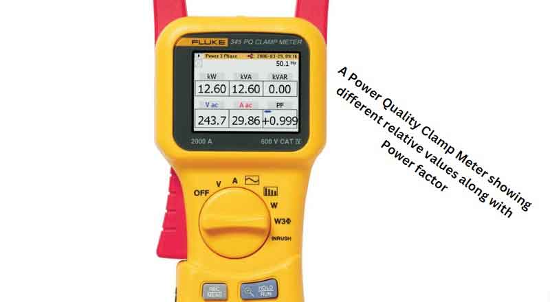
It must be kept in mind that this type of clamp meter gives us other relative parameters like apparent power, reactive power, active power, etc.
Additionally, voltage and current can also be calculated easily.
2. Power Factor Meter or Power Quality Analyzer
This instrument is an additional instrument besides a clamp meter for calculating the power factor. We can also calculate other important parameters through it.
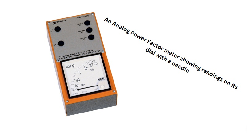
However, having a separate instrument for calculating only one parameter is not advised. Still, it is one of the best instruments for power quality analysis.
By calculating the power factor through any of these two instruments, we simply multiply the power factor with the product of current and voltage. This will give us the real power consumption of the load.
Conclusion
Electric power is the fourth essential electric parameter besides voltage, current, and resistance. We can define it as the rate of electric energy supplied to a circuit.
We calculate the power in watts, kilowatts, and kilowatts-hr.
We can use a simple clamp meter to measure a resistive load’s electric power. The circuit may be either AC or DC.
The real problem arises in AC circuits with the inductive and capacitive loads. Here, we will calculate the power factor of the load before measuring power.
The power factor is the ratio of active power and apparent power. Its value lies from 0 to 1 with 1 being the best and 0 being the worst.
The power factor can be calculated through a power clamp meter or power quality analyzer. The current value through the load and voltage across the load can easily be calculated using a clamp meter.
Now, by multiplying voltage, current, and power factor; we can calculate the value of electric power.
Other useful posts:
